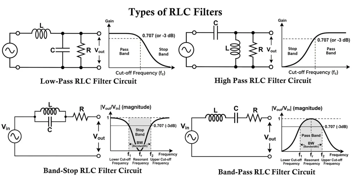
RLC filters are advanced frequency-selective circuits in electronics that utilize a resistor (R), inductor (L), and capacitor (C) to control the passage of different frequency components. By incorporating resistance along with inductance and capacitance, RLC filters provide more precise control over bandwidth, damping, and resonance characteristics compared to LC filters. Unlike LC filters, which ideally […]
Tag: frequency selective circuits
LC Filters: Circuit Diagram, Working, Types, and Applications
LC filters are widely used frequency-selective circuits in electronics that utilize an inductor (L) and a capacitor (C) to allow certain frequency components to pass while blocking others. Unlike RC filters, LC filters rely on the interaction between inductive reactance and capacitive reactance, making them highly effective in radio frequency (RF), power electronics, and communication […]
RL Filters: Circuit Diagram, Working, Types, and Applications
RL Filter Circuit is a fundamental passive filtering circuits that use a resistor (R) and an inductor (L) to control signal frequency. Like RC filters, RL filters are first-order filters, but instead of capacitive reactance, they rely on inductive reactance, which increases with frequency. Because of their simple structure and predictable frequency behavior, RL filters […]
RC Filters: Circuit Diagram, Working, Types and Applications
RC filters are the most fundamental signal-processing circuits in electronics. It uses a combination of a resistor (R) and a capacitor (C) to selectively allow or suppress signals based on their frequency. Despite its simplicity, the RC filter plays a crucial role in almost every electronic system, from basic audio amplifiers to complex communication and […]


