RLC filters are advanced frequency-selective circuits in electronics that utilize a resistor (R), inductor (L), and capacitor (C) to control the passage of different frequency components. By incorporating resistance along with inductance and capacitance, RLC filters provide more precise control over bandwidth, damping, and resonance characteristics compared to LC filters.
Unlike LC filters, which ideally operate with minimal losses, RLC filters include resistance that introduces energy dissipation, making them highly useful for controlling stability, transient response, and selectivity in practical circuits.
Filtering plays a crucial role in electronic systems to:
- Remove unwanted frequency components
- Reduce noise and interference
- Stabilize signals
- Shape signal bandwidth
Without proper filtering, circuits may experience distortion, oscillations, or instability, especially in high-frequency and communication systems.
Related Articles:
- Types of Filter Circuits: Working Principles, Formula & Applications
- Inductive Reactance and Capacitive Reactance Explained
- LC Filters: Circuit Diagram, Working, Types, and Applications
- Passive RC Filters: Circuit Diagram, Types, Working & Applications
- RL Filters: Circuit Diagram, Working, Types, and Applications
What Is an RLC Filter?
An RLC filter is a passive filter composed of a resistor, inductor, and capacitor arranged to shape the frequency response of electrical signals.
- RLC filters are commonly used when:
- Precise frequency selection is required
- Controlled bandwidth is needed
- Stability and damping are important
- Resonance-based filtering is desired
- RLC filters are widely used in:
- Radio frequency (RF) tuning circuits
- Audio signal processing
- Communication systems
- Oscillators and resonance circuits
- Power electronics and signal conditioning
Historically, RLC circuits evolved alongside LC circuits but became more practical due to the inclusion of resistance, which helps control quality factor (Q) and prevents excessive oscillations.
- Passive vs Active Filters
- Passive Filters
- Use R, L, and C components
- Do not require external power
- Cannot amplify signals
- Simple and reliable
- Active Filters
- Use operational amplifiers with passive components
- Require external power
- Provide amplification
- Offer better control over gain and response
- Passive Filters
Order of RLC Filters
RLC filters are classified as second-order filters because they contain two energy storage elements (inductor and capacitor).
- Characteristics:
- Roll-off rate: 40 dB per decade
- Sharper frequency response than RC or RL filters
- Can exhibit resonance and peak response
- Bandwidth depends on resistance
- Advantage Over LC Filters
- The inclusion of resistance introduces:
- Controlled damping
- Adjustable bandwidth
- Reduced oscillations
- Practical and stable operation
Passive Components of RLC Circuit
An RLC filter is constructed using three passive components Resistor (R), Inductor (L) and Capacitor (C). Each component contributes uniquely to the overall behavior of the filter.
Resistor (R)
A resistor is a passive component that opposes the flow of electric current and dissipates energy in the form of heat.

- The voltage-current relationship is given by: V = IR
- R = resistance (Ohm)
- I = current (Ampere)
- Role in RLC Filters:
- Controls damping of the circuit
- Determines bandwidth
- Reduces oscillations and overshoot
- Affects the sharpness of resonance
Inductor (L)
An inductor stores energy in the form of a magnetic field when current flows through it.
- The voltage across an inductor is: V = L/di/dt
- L = inductance (Henry)
- I = current (Ampere)
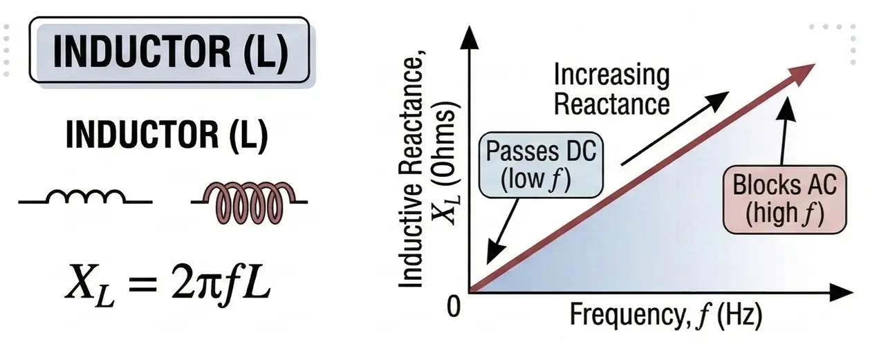
Inductors resist changes in current and exhibit frequency-dependent reactance.
- Inductive Reactance
- The opposition offered by an inductor to AC is: XL = 2πf L
- f = frequency (Hz)
- L = inductance (H)
- Key Behavior:
- Increases with frequency
- Blocks high-frequency signals
- Allows low-frequency signals
- The opposition offered by an inductor to AC is: XL = 2πf L
Capacitor (C)
A capacitor stores energy in the form of an electric field.
- The charge stored is: Q = CV
- C = capacitance (Farad)
- V = voltage (Volt)
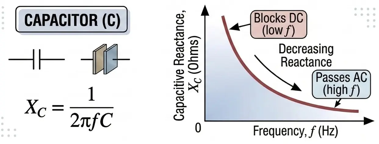
Capacitors oppose changes in voltage and allow high-frequency signals to pass.
- Capacitive Reactance
- The opposition offered by a capacitor is: XC = 1/2πfC
- f = frequency (Hz)
- C = capacitance (F)
- Key Behavior:
- Decreases with frequency
- Blocks low-frequency signals
- Allows high-frequency signals
- The opposition offered by a capacitor is: XC = 1/2πfC
Frequency Domain Concept in RLC Filters
Resonance in RLC Filters
An RLC filter consists of a resistor (R), inductor (L), and capacitor (C). Like LC circuits, energy is exchanged between the magnetic field of the inductor and the electric field of the capacitor. However, the presence of resistance introduces damping, which significantly affects resonance behavior.
RLC filters operate based on the combined impedance behavior of resistance, inductance, and capacitance.
- Inductors oppose high frequencies
- Capacitors oppose low frequencies
- Resistors control energy loss and damping
The total impedance of an RLC circuit determines how signals of different frequencies are treated.
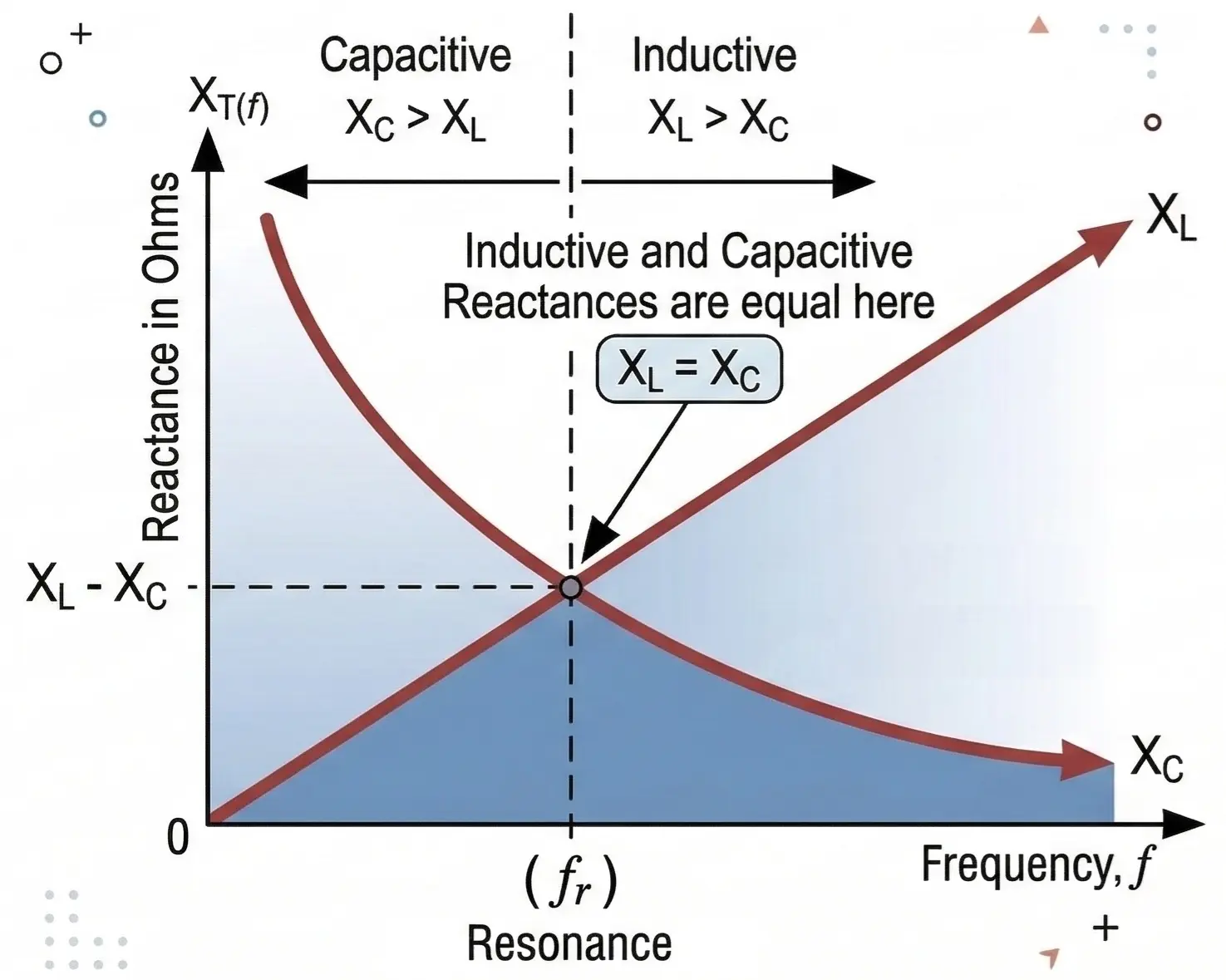
At resonance, the inductive reactance equals the capacitive reactance:
XL = XC
- XL = 2πfL
- XC = 1 / (2πfC)
At this point:
- The circuit exhibits resonance
- Maximum or minimum impedance occurs (depending on configuration)
- Selective frequency response is achieved
This makes RLC filters highly suitable for tuned circuits and band selection applications.
Effects of Resistor in RLC Circuits
Unlike ideal LC circuits, RLC circuits exhibit controlled resonance due to resistance.
- Series RLC Circuit
- Net reactance becomes zero
- Total impedance becomes minimum → Z = R
- Current becomes maximum
- Voltage across L and C can be high but limited by damping
- Energy oscillations decay over time due to resistive loss
- Parallel RLC Circuit
- Net impedance becomes maximum
- Current drawn from the source becomes minimum
- Circuit behaves like a rejector at resonance
- Energy exchange still occurs but is damped
Resonant Frequency
The resonant frequency of an RLC circuit is:
f₀ = 1 / (2π√(LC))
Where:
- f₀ = Resonant frequency (Hz)
- L = Inductance (H)
- C = Capacitance (F)
At this frequency:
- XL = XC
- Reactive effects cancel each other
- Circuit behaves purely resistive
Quality Factor (Q)
The Quality Factor (Q) defines the sharpness of resonance and depends on resistance.
For Series RLC Circuit: Q = (1 / R) √(L / C)
For Parallel RLC Circuit: Q = R √(C / L)
- Interpretation of Q
- High Q:
- Sharp resonance
- Narrow bandwidth
- Low energy loss
- High selectivity
- Low Q:
- Broad resonance
- Wide bandwidth
- Higher energy dissipation
- Less selective
- High Q:
- Resistance plays a crucial role:
- Higher resistance → Lower Q (more damping)
- Lower resistance → Higher Q (less damping)
Bandwidth in RLC Filters
Bandwidth defines the range of frequencies over which the filter effectively operates.
Bandwidth (BW) = f₂ − f₁
- f₁ = Lower cutoff frequency
- f₂ = Upper cutoff frequency
For RLC circuits: BW = f₀ / Q
- Bandwidth is inversely proportional to Q
- Higher Q → Narrow bandwidth
- Lower Q → Wide bandwidth
- Cutoff points occur at −3 dB (half power points)
Selectivity
Selectivity is the ability of an RLC filter to isolate a desired frequency while rejecting nearby frequencies.
- High Q → High selectivity
- Low Q → Poor selectivity
In communication systems (like radio receivers), RLC filters are used to:
- Select one frequency channel
- Reject adjacent signals
- Improve signal clarity
Key Parameters Summary
- Resonant Frequency: Frequency where XL = XC
- Quality Factor (Q): Sharpness of resonance
- Bandwidth: Frequency range passed
- Selectivity: Ability to reject nearby frequencies
- Important relationship:
- High Q → Narrow bandwidth → High selectivity
- Low Q → Wide bandwidth → Low selectivity
Frequency Response of RLC Filters
RLC filters provide more controlled frequency response compared to LC, RL and RC filters due to resonance and damping effects.
- Low-Pass RLC Filter
- Allows low frequencies to pass
- Attenuates high frequencies beyond cutoff
- Roll-off rate: −40 dB/decade
- Smoother transition due to resistance
- High-Pass RLC Filter
- Blocks low frequencies
- Allows high frequencies to pass
- Response increases near cutoff frequency
- Better stability compared to LC due to damping
- Unlike LC filters
- RLC filters do not produce infinite peaks at resonance
- Resistance limits current and voltage
- Provides controlled, practical response
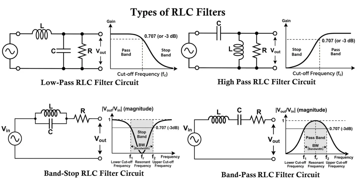
Types of RLC Filters
RLC filters can be configured in multiple ways depending on how the resistor (R), inductor (L), and capacitor (C) are connected in the circuit. These configurations affect the impedance characteristics, filtering performance, resonance behavior, bandwidth, damping, and suitability for different applications.
RLC filters can be configured in series or parallel in several ways depending on the required frequency response. The most common types are:
- Low-Pass RLC Filter
- High-Pass RLC Filter
- Band-Pass RLC Filter
- Band-Stop RLC Filter
The most common RLC filter designs are:
- L-type filters
- π (Pi) filters
- T-type filters
Each of these structures can be used to implement low-pass, high-pass, band-pass, or band-stop filters depending on the arrangement of:
- Inductive reactance (XL)
- Capacitive reactance (XC)
- Resistance (R)
These reactances behave differently with frequency:
- Inductive reactance increases with frequency
- Capacitive reactance decreases with frequency
- Resistance remains constant but controls energy dissipation
RLC networks can therefore be designed to control signal transmission over specific frequency ranges with controlled damping and stability.
Important Role of Resistance in RLC Filters
Unlike LC filters, RLC filters include resistance which introduces energy loss (damping) into the circuit.
This results in:
- Controlled resonance (no infinite current or voltage peaks)
- Adjustable bandwidth
- Reduced oscillations and ringing
- Improved stability in practical circuits
- Better control over transient response
Because of resistance:
- Resonance becomes finite and stable
- Bandwidth becomes controllable
- Selectivity depends on Q factor
- Energy is gradually dissipated instead of continuously oscillating
RLC Placement Rule for Impedance Matching
In impedance-matching networks (such as an L-section network), the placement of components follows a similar guideline as LC filters but includes resistance for stability:
- Low-impedance side (ZL) → Inductor
- High-impedance side (ZH) → Capacitor
- Resistor → Used to control damping and regulate energy flow
- An inductor is placed near the low-impedance side because:
- It opposes changes in current
- Helps increase the effective impedance seen by the source
- A capacitor is placed near the high-impedance side because:
- It provides a low-reactance path for AC signals
- Helps reduce the effective impedance
- The resistor is included to:
- Control the rate of energy dissipation
- Prevent excessive oscillations
- Stabilize the circuit response
- Improve bandwidth control
This arrangement enables the network to:
- Transform one resistance into another (impedance matching)
- Maintain maximum power transfer
- Achieve stable and controlled circuit operation
- Provide predictable frequency response
RLC Low-Pass Filter (LPF)
An RLC Low-Pass Filter allows signals with frequencies below a certain cutoff frequency to pass while attenuating higher-frequency components.
Unlike LC filters, the presence of resistance in RLC filters introduces damping, resulting in a smoother and more stable frequency response.

The typical RLC low-pass filter consists of:
- Inductor connected in series with the input
- Capacitor connected in parallel with the output
- Resistor present either:
- In series with the circuit, or
- As a load resistance across the output
Working Principle
The operation of the RLC low-pass filter depends on the combined frequency response of all three components.
- At low frequencies:
- Inductive reactance is very small
- Capacitive reactance is very large
- Resistance causes minimal voltage drop
- The signal passes easily through the inductor to the output
- At high frequencies:
- Inductive reactance increases significantly
- Capacitive reactance becomes very small
- The capacitor provides a low-impedance path to ground
- High-frequency signals are diverted away from the load
- Resistance limits current and prevents sharp oscillations
- Result:
- Low-frequency signals appear at the output
- High-frequency signals are attenuated
- Output waveform is smoother compared to LC filter
Cutoff Frequency
The cutoff frequency of an RLC low-pass filter is approximately equal to the resonant frequency of the LC section:
fc ≈ 1 / (2π√(LC))
However, in practical RLC circuits:
- Resistance slightly shifts the cutoff frequency
- The response becomes less sharp due to damping
- No infinite resonance peaks
- No excessive voltage build-up
- Controlled energy dissipation
- Improved stability in real circuits
Applications
- Power supply ripple filtering
- Switch-mode power supplies (SMPS)
- Audio signal smoothing
- RF signal conditioning
- EMI noise reduction
Low-Pass RLC Filter Configurations
Low-pass RLC filters allow low-frequency signals to pass while attenuating high-frequency signals. They are widely used in power electronics, audio systems, and RF circuits, where stable and controlled filtering is required.
L-Type Low-Pass RLC Filter
This is the simplest RLC filter configuration.

- Series Inductor → Shunt Capacitor → Load Resistance
- Input ZL → L → C → Output ZH
- Input ZH → C → L → Output ZL
- Working
- At low frequencies:
- Inductive reactance is small
- Capacitive reactance is large
- Signal passes to output
- At high frequencies:
- Inductive reactance increases
- Capacitive reactance decreases
- High-frequency components are shunted to ground
- Role of Resistance:
- Limits current
- Prevents oscillations
- Smooths output response
Applications: SMPS output filtering, DC power supply smoothing and Basic RF filtering.
π (Pi) Low-Pass RLC Filter
The π filter consists of two capacitors and one inductor, along with resistance for damping, forming a structure resembling the Greek letter π.

- Shunt Capacitor → Series Inductor → Shunt Capacitor
- Input ZH → C → L → C → Output ZH
- Working
- First capacitor reduces incoming high-frequency noise
- Inductor blocks high-frequency currents
- Second capacitor smooths the output signal
- Role of Resistance:
- Controls ripple
- Prevents resonance overshoot
- Improves stability
- Role of Resistance:
Advantages: Better ripple suppression than L-type, improved filtering performance, and reduced noise and harmonics.
Applications: Power supply filtering, audio circuits, and high-frequency noise suppression.
T-Type Low-Pass RLC Filter
The T filter consists of two inductors and one capacitor, along with resistance, arranged in a T configuration.

- Series Inductor → Shunt Capacitor → Series Inductor
- Input ZL → L → C → L → Output ZL
- Working
- First inductor blocks high-frequency signals
- Capacitor shunts unwanted frequencies to ground
- Second inductor further reduces high-frequency components
- Role of Resistance:
- Provides damping
- Improves impedance matching
- Stabilizes circuit behavior
Advantages: Better attenuation than L-type, improved impedance matching, and suitable for high-frequency applications.
Applications: RF communication systems, signal filtering networks, and transmission line matching.
RLC High-Pass Filter (HPF)
An RLC High-Pass Filter allows signals with frequencies above the cutoff frequency to pass while attenuating lower-frequency components.
Unlike LC filters, the inclusion of resistance in RLC filters introduces damping, resulting in a smoother frequency response and improved circuit stability.

A typical RLC high-pass filter consists of:
- Capacitor connected in series with the input
- Inductor connected in parallel with the load
- Resistor present either:
- As a load resistance, or
- In series for damping control
Working Principle
- At low frequencies:
- Capacitive reactance is very high
- The capacitor blocks low-frequency signals
- Output voltage becomes very small
- Inductor provides a low-reactance path for low-frequency signals to ground
- Resistance ensures controlled current flow
- At high frequencies:
- Capacitive reactance becomes very small
- Signals pass easily through the capacitor
- Inductor presents high reactance
- High-frequency signals are prevented from flowing to ground
- Resistance stabilizes the output and prevents oscillations
- Result:
- High-frequency signals appear at the output
- Low-frequency signals are attenuated
- Output response is smoother compared to LC filter
- RLC Behavior
- No sharp or infinite peaks
- Reduced ringing and overshoot
- Controlled transition near cutoff frequency
- Improved stability in practical circuits
Applications: RF signal coupling, audio crossover circuits, removing low-frequency noise, communication systems, and signal conditioning.
High-Pass RLC Filter Configurations
High-pass RLC filters allow high-frequency signals to pass while blocking low-frequency components. They are widely used in RF circuits, audio systems, and communication networks, where stable filtering is required.
L-Type High-Pass RLC Filter
This is the simplest RLC high-pass filter configuration.

- Shunt Inductor → Series Capacitor → Load Resistance
- Input ZL → L → C → Output ZH
- Input ZH → C → L → Output ZL
- Working
- At low frequencies:
- Capacitive reactance is high
- Signal is blocked
- Inductor provides path to ground
- At high frequencies:
- Capacitive reactance decreases
- Signal passes through capacitor
- Inductor blocks high-frequency path to ground
- Role of Resistance:
- Controls damping
- Prevents oscillations
- Improves stability
Applications: RF coupling circuits, signal filtering networks, and communication systems.
π-Type High-Pass RLC Filter
The π filter consists of two inductors and one capacitor, along with resistance for damping.

- Shunt Inductor → Series Capacitor → Shunt Inductor
- Input ZL → L → C → L → Output ZL
- Working
- Inductors block low-frequency signals
- Capacitor allows high-frequency signals to pass
- Resistance controls energy loss and stabilizes output
Advantages: Improved high-frequency response, better attenuation of low frequencies, and more stable than simple L-type filter.
Applications: RF signal processing, communication circuits, and high-frequency filtering.
T-Type High-Pass RLC Filter
The T filter consists of two capacitors and one inductor, along with resistance, arranged in a T configuration.

- Series Capacitor → Shunt Inductor → Series Capacitor
- Input ZH → C → L → C → Output ZH
Working
- Capacitors pass high-frequency signals
- Inductor blocks low-frequency components
- Resistance ensures stable and controlled response
Advantages: Better impedance characteristics, improved stability, and suitable for high-frequency applications.
Applications: Antenna coupling, RF communication systems, and signal transmission networks.
RLC Band-Pass Filter (BPF)
A Band-Pass RLC Filter allows signals within a specific range of frequencies to pass while rejecting frequencies outside this range.
Unlike LC filters, RLC band-pass filters include resistance, which controls bandwidth, selectivity, and stability, making them more practical for real-world applications.
Circuit Configuration
A band-pass RLC filter is typically formed by combining:
- A series resonant circuit → passes frequencies nearby (fr)
- A parallel resonant circuit → attenuates frequencies above and below resonance
- A resistor → controls damping and bandwidth
The most common configuration uses a series RLC network connected in the signal path: Input → R–L–C (series) → Output
Output is usually taken across the resistor, where maximum voltage appears at resonance.
Working Principle
- At resonant frequency:
- Inductive reactance equals capacitive reactance XL = XC
- The impedance of the series RLC circuit becomes minimum
- Maximum current flows through the circuit
- Maximum voltage appears across the resistor
- The desired frequency passes through the circuit
- At frequencies below resonance:
- Capacitive reactance dominates
- Circuit impedance increases
- Signal transmission decreases
- At frequencies above resonance:
- Inductive reactance dominates
- Circuit impedance again increases
- Signal transmission decreases
- Role of Resistance
- Controls bandwidth (BW)
- Determines Quality Factor (Q)
- Limits peak current
- Prevents excessive oscillations
- Provides stable frequency response
- Result:
- Only a specific band of frequencies around the resonant frequency passes
- Frequencies outside this band are attenuated
- Response is smooth and controlled due to resistance
- Bandwidth:
- The width of the passband: BW = f2 – f1
- Bandwidth for RLC circuits: BW = R / (2πL)
Applications
- Radio receivers for channel selection
- Wireless communication systems
- Signal processing circuits
- Frequency-selective amplifiers
- Tuned amplifier stages
Band-Pass RLC Filter Configurations
Band-pass RLC filters allow a specific range of frequencies to pass while attenuating frequencies below and above that range. They are widely used in communication systems, RF circuits, and signal processing applications.
Series Resonant Band-Pass RLC Filter Circuit

- Series R–L–C connected in the signal path
- Input → R – L – C → Output
- Working
- At the resonant frequency:
- Inductive reactance equals capacitive reactance
- Circuit impedance becomes minimum
- Maximum current flows
- Maximum signal appears at output
- At frequencies above and below resonance:
- Impedance increases
- Signal is attenuated
- Key Features
- Sharp resonance (depends on Q)
- Controlled peak due to resistance
- Stable operation
Applications: RF tuning circuits, frequency selection stages, and signal filtering.
Parallel Resonant Band-Pass RLC Filter Circuit

- Parallel LC network with resistance
- Input → (L || C) with R → Output
- Working
- At the resonant frequency:
- Parallel LC circuit presents very high impedance
- Signal is not shunted to ground
- Output voltage is maximum
- At frequencies outside resonance:
- Impedance decreases
- Signals are partially bypassed or attenuated
- Role of Resistance
- Controls sharpness of resonance
- Limits peak voltage
- Stabilizes circuit
Applications: Radio receivers, oscillators, RF amplifiers, and frequency selection circuits.
RLC Band-Stop Filter (Notch Filter)
A Band-Stop RLC Filter blocks signals within a specific frequency range while allowing frequencies outside this range to pass. It is often referred to as a notch filter when the rejected band is narrow.
Unlike LC filters, the presence of resistance introduces damping, which controls the depth and width of the notch, making the filter more stable and practical.
Circuit Configuration
A band-stop RLC filter is usually formed using a parallel resonant circuit along with resistance.
Input → Parallel RLC Network → Output
The resistor may be in series with the circuit, or across the load to control damping and bandwidth.
Working Principle
- At resonant frequency:
- Inductive reactance equals capacitive reactance XL = XC
- The impedance of the parallel RLC circuit becomes very high
- Signal transmission is greatly reduced
- The unwanted frequency is effectively blocked
- At frequencies below resonance:
- Capacitive reactance dominates
- Inductive reactance is small
- Signals pass through the inductor
- Output is maintained
- At frequencies above resonance:
- Inductive reactance dominates
- Capacitive reactance becomes small
- Signals pass through the capacitor
- Output remains available
- Result:
- A specific frequency band around resonance is rejected
- All other frequencies pass through
- The rejection band is controlled by resistance
- Role of Resistance
- Resistance plays a critical role in determining:
- Bandwidth of the notch
- Depth of attenuation
- Quality factor (Q)
- Stability of operation
- Resistance plays a critical role in determining:
- Effects of Resistance
- High resistance → Wider notch, less sharp rejection
- Low resistance → Narrow notch, sharper rejection
- Proper resistance → Controlled and stable filtering
Applications
- Removing interference in communication systems
- Eliminating power-line hum (50/60 Hz)
- Noise suppression circuits
- Audio signal processing
- EMI filtering
Band-Stop RLC Filter Configurations
Band-stop RLC filters reject a specific band of frequencies while allowing others to pass. They are widely used in communication systems, audio circuits, and noise suppression applications.
Parallel Resonant Notch Filter

- Parallel RLC connected across the signal line
- Input → (L || C, R) → Output
- Working
- At resonant frequency:
- Parallel RLC circuit presents very high impedance
- Signal cannot pass through effectively
- The unwanted frequency is blocked
- At other frequencies:
- Impedance decreases
- Signals pass normally
- Role of Resistance
- Controls notch width
- Prevents excessive resonance
- Stabilizes circuit
Applications: Noise elimination, harmonic suppression, and RF interference filtering.
Series Resonant Band-Stop RLC Filter

- Series RLC connected in the signal path
- Input → R – L – C → Output
- Working
- At resonance:
- Impedance becomes minimum
- Current increases significantly
- Voltage drop across resistor increases
- Signal at that frequency is attenuated
- At frequencies outside resonance:
- Impedance increases
- Signals pass normally
- Role of Resistance
- Limits current
- Controls attenuation depth
- Prevents instability
Applications: Communication systems, EMI suppression, and frequency rejection circuits.
Comparison of RLC Filters

| Filter Type | Passes | Blocks | Typical Use |
|---|---|---|---|
| Low-Pass | Low frequencies | High frequencies | Power supply filtering |
| High-Pass | High frequencies | Low frequencies | Audio & RF circuits |
| Band-Pass | Specific frequency band | Outside band | Radio tuning |
| Band-Stop | All except certain band | Specific band | Noise elimination |
Configurations of RLC Filters

| Filter Type | Common Circuit Forms |
|---|---|
| Low-Pass RLC | L-section, π-section, T-section |
| High-Pass RLC | L-section, π-section, T-section |
| Band-Pass RLC | Series RLC, Parallel RLC |
| Band-Stop RLC | Parallel notch, Series notch |
Design Procedure for RLC Filter
- Specify the required cutoff frequency, resonant frequency, or bandwidth
- Decide the type of filter: low-pass, high-pass, band-pass, or band-stop
- Select a convenient value of capacitor (C) or inductor (L)
Calculate the resonant frequency using: f₀ = 1 / (2π√(LC))
- Calculate resistance (R) based on required Quality Factor (Q) and bandwidth
For bandwidth: BW = f₀ / Q
- Choose standard component values (R, L, C)
- Verify performance using frequency response analysis (Bode plot / simulation)
- You can use this RLC analysis and simulation tool.
Practical Design Notes
- Lower resistance → Higher Q → Narrow bandwidth
- Higher resistance → Lower Q → Wider bandwidth
- Component selection directly affects selectivity and stability
Practical Considerations
- Resistance causes power loss and heat dissipation
- Parasitic capacitance and inductance affect high-frequency response
- Component tolerances shift resonant frequency and bandwidth
- Inductor core saturation limits performance at high current
- Resistance reduces oscillations but also reduces peak response
- Thermal variation affects resistance and circuit stability
- Physical size of inductors can be large in low-frequency designs
Advantages of RLC Filters
- Controlled and stable resonance (no infinite peaks)
- Adjustable bandwidth using resistance
- Better selectivity compared to RC and RL filters
- Suitable for both low-frequency and high-frequency applications
- Can be designed for band-pass and band-stop operations
- Improved stability due to damping
- Widely used in communication and signal processing systems
Disadvantages of RLC Filters
- More complex design compared to RC or RL filters
- Requires careful selection of resistance for proper damping
- Power loss due to resistor
- Inductors can be bulky and expensive
- Core saturation may affect performance
- Design becomes sensitive to component tolerances
- Reduced efficiency compared to ideal LC filters
Applications of RLC Filters
- Tuned circuits in radio transmitters and receivers
- RF communication systems
- Band-pass and notch filters in signal processing
- Audio equalizers and crossover networks
- Oscillator circuits
- EMI and noise suppression circuits
- Power electronics and SMPS filtering
- Frequency-selective amplifiers
RC vs RL vs LC vs RLC Comparison
| Parameter | RC Filter | RL Filter | LC Filter | RLC Filter |
|---|---|---|---|---|
| Components | Resistor + Capacitor | Resistor + Inductor | Inductor + Capacitor | Resistor + Inductor + Capacitor |
| Order | First-order | First-order | Second-order | Second-order (or higher) |
| Roll-off rate | 20 dB/decade | 20 dB/decade | 40 dB/decade | 40 dB/decade (or higher) |
| Power efficiency | Lower | Moderate | High | Moderate |
| Frequency range | Low to medium | Low to medium | High frequency | Wide range (audio to RF) |
| Size | Compact | Larger (inductor) | Larger (inductor) | Larger (multiple components) |
| Selectivity | Low | Low | High | Very high (controlled) |
| Stability | High | Moderate | Lower | High (due to damping) |
| Typical applications | Audio filtering | Current filtering | RF, power filtering | Tuned circuits, communication |
Conclusion
RLC filters are highly versatile passive filtering circuits that use a combination of resistance, inductance, and capacitance to control the frequency content of electrical signals.
Compared to LC filters, RLC filters provide controlled resonance, adjustable bandwidth, improved stability, and better practical performance.
Although they introduce power loss due to resistance and require more careful design, RLC filters are essential in modern electronics where precision, stability, and selectivity are required.
They are widely used in communication systems, audio processing, RF circuits, and signal conditioning applications making them one of the most important filter types in both analog and high-frequency electronics.
Types of Filter Circuits: Working Principles, Formula & Applications
LC Filters: Circuit Diagram, Working, Types, and Applications
RC Filters: Circuit Diagram, Working, Types and Applications
RL Filters: Circuit Diagram, Working, Types, and Applications
